




Sorry, no sales person is available right now to take your call. Pls leave a message and we will reply to you via email as soon as possible.
Differences Between Blind Vias, Buried Vias, and Through Vias, and How to Determine HDI Stage 1 to 3 / Any-Layer
2026-09-24
In PCB design and manufacturing, many hardware and layout engineers easily fall into pitfalls: confusing the HDI stage with the total PCB layer count; blindly choosing first-order HDI for 0.4 mm pitch BGAs, which leads to fanout failure later and forces a stack-up change and board re-submission; and failing to distinguish between stacked vias and staggered vias, without clearly specifying them in the board fabrication documentation, ultimately causing the board manufacturer to use the wrong process and delaying the project schedule.
Core Concept Correction: The "stage" of HDI is not equal to the "total layer count" of the PCB. The HDI stage represents the number of outer-layer build-up cycles (lamination + laser-drilled blind vias), and has no direct correspondence to the total number of board layers.
I. Core Differences Between Blind Vias, Buried Vias, and Through Vias
1. Blind Via
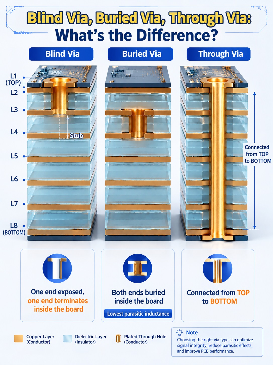
A blind via is drilled downward from the PCB surface or bottom layer by laser and terminates at a certain inner layer; it does not penetrate the entire board. Visually, the via opening is visible on only one side and not on the opposite side.
Example: L1-L2 and L8-L7 connections in an 8-layer board.
Advantages: Short via depth, extremely small stub, low high-speed signal reflection; does not occupy BGA pads on the opposite side, making it the main solution for BGA fanout.
Process: Mainstream method uses laser drilling.
2. Buried Via
A buried via is completely hidden inside the PCB, located between inner-layer core boards, with no via opening visible on either the top or bottom surface.
Example: L2-L3 and L4-L5 connections in an 8-layer board.
Advantages: Does not occupy surface space at all, minimal parasitic inductance, excellent high-speed performance.
Process: Inner-layer core boards must first be drilled and plated, then multiple core boards are laminated together. After lamination, it cannot be observed from the outside.
3. Through Via
A through via is drilled directly from the top layer through to the bottom layer, penetrating all PCB layers, with via openings visible on both the front and back sides.

II. How to Distinguish HDI First Order / Second Order / Third Order / Any Order?
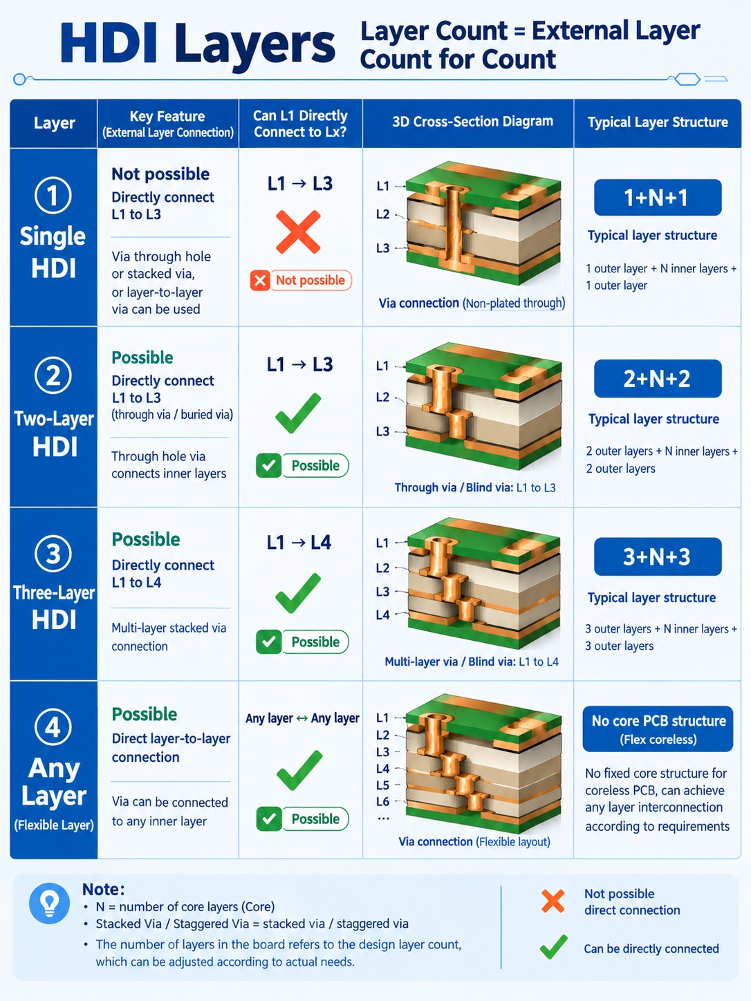
Core definition: HDI stage = the number of outer-layer build-up cycles (lamination + laser-drilled blind vias).
1. First-Order HDI (Marking Format: 1+N+1)
Only one outer-layer build-up is performed. Blind vias can only connect the surface layer to the immediately adjacent sub-surface layer (such as L1-L2, Ln-L(n-1)), and cannot directly connect across layers (such as L1-L3).
Structure: The middle is an N-layer core board, with one layer of dielectric laminated on both the top and bottom, and laser blind vias only open the adjacent outer layers.
Applicable scenarios: BGA pitch ≥ 0.5 mm.
Characteristics: Lowest cost, mature mass-production process, widely used in consumer electronics and industrial control boards.
2. Second-Order HDI (Marking Format: 2+N+2)
Two build-up cycles are completed, enabling the surface layer to directly connect to L3. Second-order HDI is divided into two structures, and this is the most error-prone part in engineering:
Stacked Via: The L1-L2 blind via and the L2-L3 blind via are vertically aligned and stacked, and the middle L2 pad must be electroplated and filled. The routing path is the shortest, and the stub is smaller; however, alignment difficulty for the board manufacturer is high, reliability risk is slightly higher, and the price is more expensive.
Note: Stacked vias must explicitly require electroplated filling, and resin plugging alone is strictly prohibited.
Staggered Via: The two blind vias L1-L2 and L2-L3 are offset left and right and are not in the same vertical position. The process is simple, yield is high, and cost is lower than stacked vias; however, it occupies valuable routing channel space inside the BGA.
3. Third-Order HDI (Marking Format: 3+N+3)
Three build-up cycles are completed, and the surface layer can directly connect to L4, with blind vias stackable up to three levels deep.
Applicable scenarios: 0.3 mm and 0.35 mm ultra-fine-pitch BGAs, AI computing chips, high-speed server motherboards.
Characteristics: Cost rises further, and yield relatively decreases.
4. Any-Layer Interconnect (Any-Layer / Any Order)
Abandoning the traditional "central large core board N" architecture, it adopts a layer-by-layer build-up method. Laser blind vias can be drilled between any adjacent two layers, and any two layers can be directly interconnected without needing through-via transition.
Advantages: Almost no stub exists, reaching the ceiling of high-speed performance; perfectly suitable for fanout of ultra-dense BGAs below 0.3 mm.
Characteristics: Extremely high price, mainly used for high-end smartphone motherboards, AI computing cards, etc.

III. Key Points for HDI PCB Design Selection and Pitfall Avoidance

1. BGA Pitch Matching HDI Process (The Most Critical Selection Point)
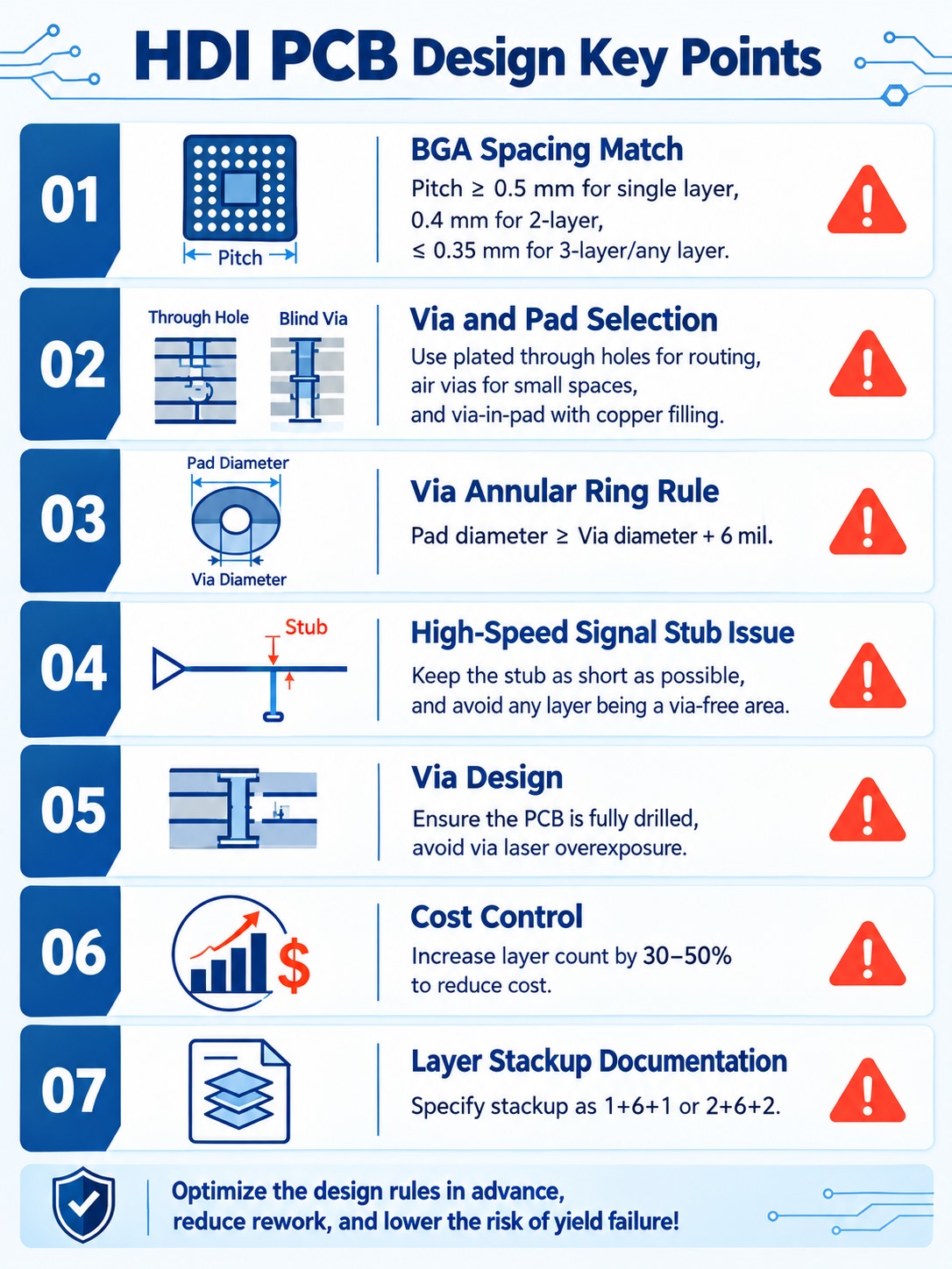
Pitch ≥ 0.5 mm: First-order HDI is sufficient; do not blindly use second-order and add ineffective cost.
Pitch = 0.4 mm: Prefer second-order staggered vias for controllable cost; choose second-order stacked vias only when BGA routing space is extremely tight.
Pitch ≤ 0.35 mm: Third-order or Any-Layer must be used.
2. Trade-off Principles for Second-Order Stacked Vias vs. Staggered Vias
Prioritizing cost control and production reliability → Choose second-order staggered vias.
Extremely tight routing channels inside the BGA and insufficient space → Choose second-order stacked vias, and it must be clearly marked in the board fabrication documentation: "Stacked vias require electroplated filling; resin plugging is rejected."
3. Laser Blind Via Diameter and Pad Rules
The conventional minimum laser blind via diameter is 0.1 mm (4 mil).
The pad diameter must be at least 6 mil larger than the via diameter, with a single-side annular ring of at least 3 mil, to prevent pad breakage and open circuits.
Avoid drawing blind via pads as large as through-via pads, so as not to waste the narrow space in the BGA area.
4. Focus on Stub for High-Speed Signals
The shorter the blind via, the smaller the stub, the lower the signal reflection, and the better the high-speed performance.
Path length comparison: Stacked vias < staggered vias; Any-Layer has almost no stub, making it most suitable for ultra-high-speed links such as DDR5, PCIe 5.0, and high-speed SerDes.
5. Precautions for Using Buried Vias
Buried vias are drilled during the inner-layer core board stage and cannot be processed later by laser.
Buried vias are suitable for long-distance inner-layer interconnection; high-speed BGA fanout should preferentially use blind vias to reduce parasitic effects.
6. Cost and Lead Time Red Lines
For each increase in HDI stage, PCB procurement price usually rises by 30% to 50%, while lead time lengthens and yield decreases.
Selection iron rule: If first-order can be used, do not use second-order; if staggered vias can be used, do not use stacked vias; if second-order can be used, do not use Any-Layer.
7. Be Sure to Clearly Describe the Process in Output Production Documentation
Many engineers only output the stack-up sequence and ignore the HDI process description. It must be clearly marked in the board fabrication instructions, for example: "1+6+1 first-order HDI," "2+6+2 second-order staggered HDI." If it is not clearly written, the board manufacturer will process according to the default process, which can easily lead to process mismatch and scrapping of the entire batch.
The core of HDI selection is not "how many layers the board has," but the balance among BGA pitch, fanout channels, stub requirements, cost, and lead time. Only by clarifying the differences between blind vias, buried vias, and through vias, understanding the structural differences among first-order, second-order, third-order, and Any-Layer, and accurately expressing process requirements in the board fabrication documentation, can risks such as later stack-up changes, board re-submission, and even scrapping be avoided.
trending news
Contact Us