




Sorry, no sales person is available right now to take your call. Pls leave a message and we will reply to you via email as soon as possible.
How to Properly Design the Flex-Rigid Transition Zone in Rigid-Flex PCBs? A technical guide for reliable interconnect design
2026-08-10
In the PCB industry, rigid-flex boards offer unmatched 3D routing freedom and enhanced integration reliability, making them ideal for wearables, medical devices, aerospace, and other high-end applications. Their unique construction seamlessly combines flexible circuits with rigid support sections—and the critical interface between the two, known as the transition zone, is both the backbone and the weakest link of the entire assembly.
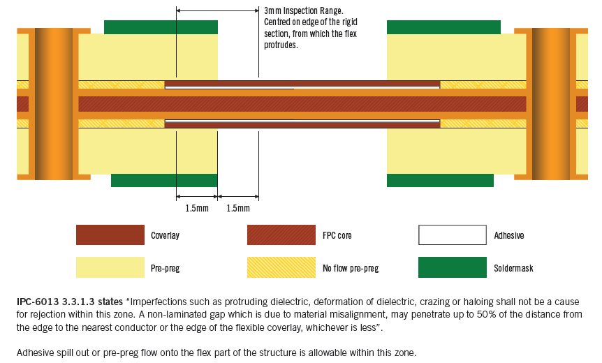
Per IPC-6013, this transition region is centered on the rigid board edge axis, with a typical total width of 3 mm. It concentrates mechanical and thermal stresses, presenting risks throughout manufacturing, assembly, and the product's entire service life. Improper design can lead to cracks, delamination, or functional failure. This article explores the essential design and manufacturing considerations for this zone to help you avoid these pitfalls.

Part 1: Why the Transition Zone Is Challenging – Root Causes from a Manufacturing Perspective
The fabrication of rigid-flex PCBs is inherently more complex than standard rigid boards. A key step involves laminating the flexible layers independently before bonding them to the rigid sections via a secondary pressing process. To prevent resin from flowing into the flexible area during lamination, spacers must be placed in the stack-up and later milled out. This special sequence creates inherent defect risks in the transition zone, as summarized below:
| Defect Type | Causes and Effects |
| Cracking & Delamination | Thickness mismatch between rigid and flex sections creates a "step" where stress concentrates during bending or thermal cycling, leading to material separation, resin micro-cracks, or copper fracture. |
| Lamination Voids | To prevent resin contamination of the flex area, "low-flow / no-flow" prepreg materials must be used. Their reduced flowability often leads to voids in the transition region. |
| Resin Bleed-out | Even with low-flow materials, resin can seep from the rigid board edges. After curing, sharp protrusions may abrade or even pierce the flex circuit under dynamic bending. |
| Copper Deformation | Poor material stability in the transition zone can cause copper traces to deform, micro-crack, or delaminate due to uneven resin filling or lamination stresses. |
| Coverlay Peeling Risk | The adhesion between coverlay and FR-4 is suboptimal. If the coverlay extends into the transition zone, it is highly prone to delamination at the interface. |
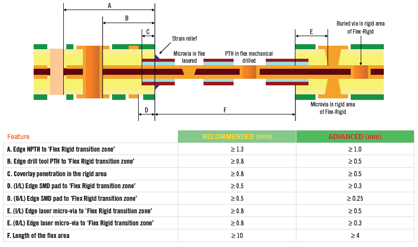
Key Design Insight: Given the inevitable manufacturing defects in this region, the most fundamental principle is to treat it as a keep-out zone—avoid placing any critical traces, pads, or vias in this area.
Part 2: How to Design a Reliable Transition Zone – Engineering Best Practices
A successful design requires a closed-loop approach integrating material selection, layout, and process optimization.
1. Design Collaboration and Planning
· Engage your supplier early: Interface with your PCB manufacturer's technical team during the concept stage. Manufacturable safe widths and tolerances for the transition zone vary by vendor capability.
· Define bending scenarios clearly: Distinguish between "one-time installation bending" and "dynamic/repeated bending." The latter demands far stricter control over planarity, resin bleed, and material fatigue resistance.
2. Layout and Stack-up Optimization
·Trace routing rules: All traces crossing the transition zone should be routed perpendicular to the bend axis (i.e., along the bend direction) and use teardrop-shaped transitions to distribute stress gradually.
·Neutral axis design: In multi-layer flex constructions, place conductive layers as close as possible to the neutral axis of the stack-up thickness to substantially reduce tensile/compressive stresses during bending.
· Apply stiffeners: Add a stiffener on the rigid side near the junction to support the flex root and prevent tearing.
3. Material and Boundary Treatment
· Coverlay windowing design: Terminate the coverlay outside the rigid board boundary, maintaining a minimum clearance of 0.5–1 mm from the rigid solder mask to prevent delamination.
· Stepwise lamination: Use stepped openings instead of a single vertical line at material interfaces to smooth stress transitions.
Part 3: Closing the Loop – from Design to Production Quality

1. Manufacturing Process Control Essentials
· Precision routing control: The routing profile, particularly when releasing the flex section, must be precisely controlled. Poor routing results in dielectric protrusions or burrs that impair bending performance.
· Agree on acceptable defects: Establish a clear mutual understanding with your manufacturer regarding acceptable defect criteria per IPC standards for your specific application. For high-reliability products, demand cross-section analysis reports for the transition zone.
2. Reliability Verification Strategy
· Simulation: Use finite element analysis (FEA) to simulate mechanical bending and thermal cycling on the transition zone, identifying high stress points early and refining the design.
· Targeted testing:
· Dynamic bend testing: Conduct thousands to hundreds of thousands of bending cycles based on product life expectations.
· Environmental stress testing: Perform temperature/humidity cycling and thermal shock tests to verify interface stability under extreme conditions.
3. Addressing Miniaturization Trends
· As devices shrink (e.g., hearing aids, smartwatches), the design space for the transition zone becomes ever tighter. Priority should be given to optimizing the overall stack-up (using thinner materials, adjusting rigid/flex positioning) to gain space, rather than simply pushing manufacturing limits. Any design beyond standard capabilities must be backed by exhaustive prototyping and reliability data.
Conclusion
Designing the rigid-flex transition zone is ultimately an art of balancing electrical performance, mechanical reliability, and manufacturability. Success hinges on three pillars:
· Respecting manufacturing realities: Understand and avoid the inherent defect mechanisms in the transition area.
· Forward-looking design: Proactively manage stress through layout and material choices, guided by simulation and supplier feedback.
· Closed-loop verification: Validate performance against real-world application scenarios to ensure reliability throughout the product's lifecycle.
By following this systematic methodology, you can fully leverage the advantages of rigid-flex technology while delivering robust, dependable products.
Kinji brings proven rigid flex manufacturing expertise. We offer end to end technical support—from stack up recommendations to stress simulation for your transition zone. We highly recommend submitting your design files along with a description of your bending application before production. Our team will provide a tailored DFM optimization report focused on the transition region.
Contact our technical team today for a design review tailored to your project’s transition zone challenges.
trending news
Contact Us