



Sorry, no sales person is available right now to take your call. Pls leave a message and we will reply to you via email as soon as possible.
Factors Influencing the Flexural Life of FPC Flexible Circuit Boards and Paths to Reliability Improvement
2026-10-29
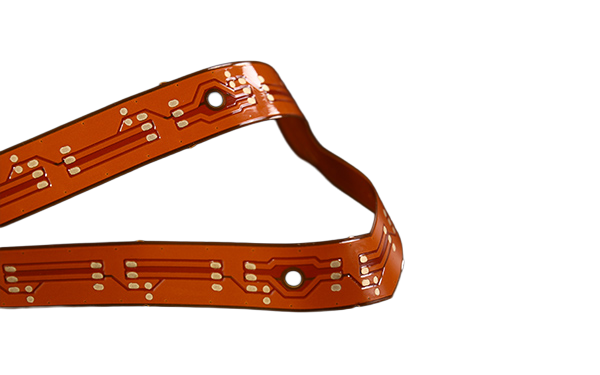
The essence of FPC flexural life is the fatigue failure of copper foil under alternating "tension–compression" stress. The two hardest variables that determine success or failure are the bend radius and the position of the copper foil within the stack-up (the neutral layer); material selection and trace layout are secondary. In the industry, a dynamic flex life of ≥100,000 cycles is generally considered acceptable, and ≥200,000 cycles is considered good; the hinge area of foldable screens has already achieved more than 400,000–500,000 cycles under specific test conditions. The above figures should be used as project target references, and the agreed test conditions and acceptance criteria shall prevail.

I. Failure Mechanisms
In a single bend, all layers of the FPC simultaneously experience multiple forms of damage, and these damage modes accelerate one another:
Copper foil traces repeatedly switch between tension and compression states, microcracks initiate at grain boundaries and gradually propagate, ultimately potentially causing an open circuit;
The PI substrate undergoes microscopic fatigue, and dimensional stability decreases;
The interface between the coverlay and the copper traces is subjected to shear stress, which may lead to delamination and blistering;
Solder pads, vias, and rigid-flex transition zones become stress concentration points and often crack first.
The key trap is that this type of failure often only becomes apparent after assembly or during use. PCBA visual inspection appears normal, and fracture occurs only after multiple bending cycles or temperature cycles, making troubleshooting and rework extremely costly. Therefore, the bend zone should be treated as an independent design domain and validation domain, and the design standards for ordinary trace areas cannot be applied to it.

II. Influencing Factors (by weight of influence)
| Factor | Influence and quantitative reference (to be verified against specific conditions) | Design/selection implications |
| Bend radius R | The most core factor. For dynamic bending, a commonly used empirical safety radius reference is R ≥ 100 × total board thickness, e.g., a total thickness of 0.1 mm corresponds to R ≥ 10 mm; actual measurements in some foldable-screen hinge areas indicate that R < 3.2 mm significantly accelerates failure | Determine the radius first, then the layout; when space is limited, prioritize reducing the bend angle rather than compressing the radius |
| R/W (radius/line width ratio) | Data indicate that R/W ≥ 10 helps keep copper strain within approximately 0.2% and, under specific conditions, improves life; right-angle transitions easily cause stress concentration | Avoid right-angle transitions; ensure that line width in the bend zone matches the radius |
| Copper foil type | Rolled annealed copper (RA), formed by repeated rolling and annealing into a flake-like crystalline structure, generally offers better ductility and flex resistance than electrodeposited copper (ED) | Prioritize RA copper foil for dynamic bend zones; for static zones, evaluate comprehensively based on cost |
| Copper foil thickness | For the same material, thinner foil generally has better flex resistance, but current-carrying and mechanical load-bearing capacity decrease, requiring trade-offs | Determine copper thickness comprehensively based on current-carrying, impedance, and life targets |
| Substrate and adhesive layer | 2L adhesive-free substrates eliminate the intermediate bonding layer, are thinner, more flexible, and have more uniform interlayer bonding, reducing stress concentration; adhesive-containing structures require attention to differences in adhesive system flexibility | Prioritize evaluation of 2L adhesive-free PI for dynamic zones; adhesive-containing solutions must be verified against specific material parameters |
| Neutral layer position | During bending, there is a neutral layer that is not subjected to tension or compression; the farther the copper foil is from the neutral layer, the greater the strain; coverlay thickness shifts the position of the neutral layer | Use coverlay thickness and stack-up symmetry to keep conductors in the bend zone as close as possible to the neutral layer |
| Trace direction | Traces in the bend zone should be distributed as perpendicular as possible to the bend axis; routing along the bend direction is a common cause of fracture | Routing direction should prioritize compliance with the bend axis; avoid long-distance routing along the bend |
| Trace shape | Arc-shaped and teardrop-shaped transitions are superior to right angles; serpentine/comb-shaped routing can serve as stress-relief structures | Use fully arc-shaped transitions and stress-relief patterns in dynamic bend zones |
| Stack-up structure | Multi-layer FPC bend zones should adopt "offset stacking" so that conductors in each layer are staggered, avoiding overlap that creates local rigid regions | Reduce interlayer overlap and local stiffness abrupt changes in the bend zone |
| Stiffener layout | The stiffness abrupt change between stiffeners (FR4/steel sheet) and flexible zones is a high-incidence failure point; trapezoidal gradual transitions are needed; the spacing of steel stiffener panelization can be evaluated according to specific processes, with some specifications referencing 3 mm and 2 mm for ordinary zones | Avoid stiffness abrupt changes in rigid-flex transition zones; make stiffener edges gradual |
| Temperature environment | High temperatures accelerate material aging and reduce flexibility; low temperatures make the substrate harder and more prone to damage during bending. Consumer electronics conventional requirements are approximately -40°C to 125°C | Verify materials and flex life according to the operating temperature range |
III. Paths to Reliability Improvement
1. Design side (largest benefit, lowest cost)
Determine the radius first, then the layout: Treat R ≥ 100 × total thickness as the empirical baseline for dynamic bending, and relax it whenever possible; when space is limited, prioritize reducing the bend angle rather than shrinking the radius.
Push the copper foil toward the neutral layer: By adjusting coverlay thickness and stack-up symmetry, bring conductors in the bend zone closer to the neutral layer—this is one of the most effective structural adjustments for improving life.
"Three don'ts" for the bend zone: no fine lines, no critical power/signal channels, and no pads or vias.
Fully arc-shaped routing + stress relief: Replace right-angle transitions with arcs or teardrops, and use serpentine/comb-shaped stress-relief structures when necessary; right-angle transitions are prohibited.
Trapezoidal gradual transitions for rigid-flex transitions: Eliminate stiffness abrupt changes between stiffener areas and flexible areas.
2. Material side
Prioritize adhesive-free 2L PI substrate + rolled copper for dynamic bend zones; for static assembly zones, PET, adhesive-containing structures, or electrodeposited copper may be selected based on comprehensive cost considerations.
Coverlay thickness should be derived backward from the life target rather than applied as a one-size-fits-all default; adhesive-containing structures require focused verification of adhesive layer flexibility and interlayer bonding reliability.
3. Process and validation side
Manufacturers may be asked to provide process capability data such as conductor thickness deviation control in the bend zone (e.g., ±10%) and minimum dielectric layer thickness (e.g., ≥25 μm); specific values shall be confirmed according to product specifications.
Design standards may follow IPC-2223 (Flexible/Rigid-Flex Design), acceptance may reference IPC-6013, and test methods may reference JIS C 5016 and IPC-TM-650 2.4.3.1 (dynamic flex testing, with adjustable angle of 90–180° and adjustable bend radius of 0.5–2 mm).
Actual measurement and judgment are mandatory. Using typical validation conditions for foldable-screen FPCs as a reference: 180°, radius 0.6 mm, frequency 30–60 cycles/min, cycles ≥400,000; acceptance criteria are resistance change ≤10%, no trace cracking or fracture, no delamination, and no open circuit. The design target may reference "line fracture rate ≤0.1% after 100,000 bending cycles."
One-sentence reminder: Do not rely solely on material upgrades to solve the problem. The industry-recognized core causes of dynamic bending failure are stress concentration and excessive trace strain, and these are primarily design issues—no matter how good the material is, if the routing direction and bend radius are designed incorrectly, it will still break.
trending news
Contact Us