



Sorry, no sales person is available right now to take your call. Pls leave a message and we will reply to you via email as soon as possible.
Analysis of Key Manufacturing Processes for Ceramic Thin/Thick Film Substrates
2026-10-16
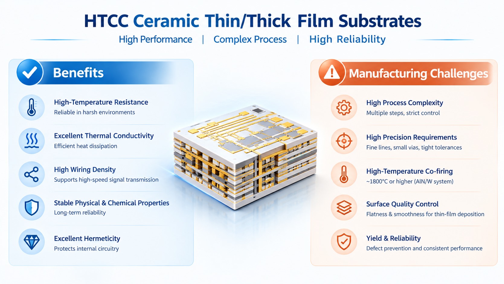
HTCC multilayer high-temperature co-fired ceramic thin-film circuit substrates are a type of hybrid integrated substrate that combines HTCC multilayer three-dimensional interconnects with fine surface thin-film metallization. They offer high structural strength, high-temperature resistance, good thermal conductivity, high wiring density, stable physical and chemical properties, and excellent hermeticity. They can be used in applications such as 400G/800G/1.6T high-speed optical modules for optical communications, microwave RF, power devices, and T/R modules.
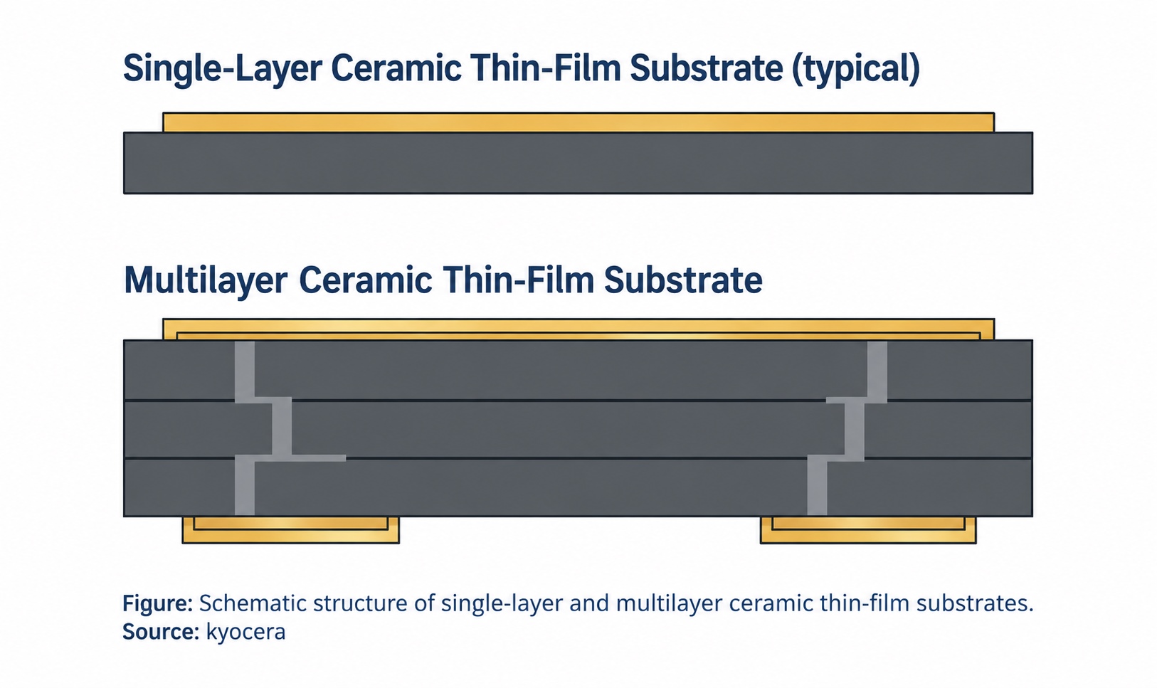
A typical multilayer co-fired ceramic thin/thick film circuit substrate usually consists of two parts: the center is an HTCC multilayer ceramic body, and the upper and lower surfaces are fine thin-film metallization wiring. Its manufacturing route is generally divided into two stages: first, a multilayer ceramic substrate is prepared through the HTCC process, and then fine circuits are fabricated on the front and back sides of the substrate through thin-film processes.

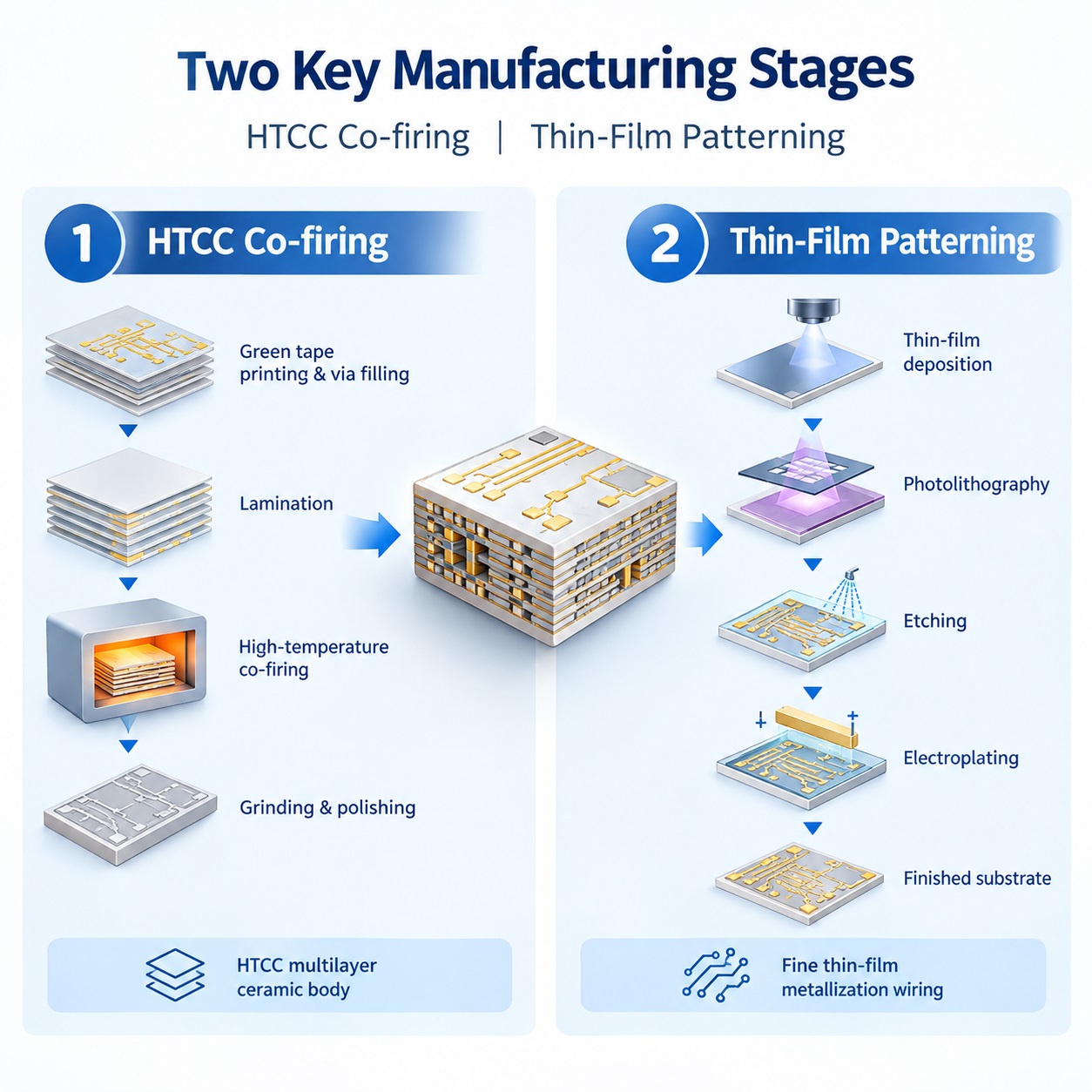
The HTCC stage mainly uses aluminum nitride green tapes and tungsten metal paste as raw materials. Metal paste is printed onto the green tape through screen printing to form circuit patterns, and via filling is used to achieve electrical interconnection between layers. Then, multilayer lamination is performed, followed by high-temperature co-firing (the aluminum nitride/tungsten system usually requires about 1800°C or higher) and surface treatment to form a monolithic ceramic substrate with a three-dimensional wiring structure. After that, grinding, polishing, and other treatments are carried out to obtain a flat, smooth ceramic surface, so that the surface roughness meets the requirements for thin-film circuit fabrication. Thin-film processes are then used to fabricate fine lines on the front and back sides of the HTCC substrate.
The full fabrication sequence is as follows:
1. Slurry preparation: Ceramic powder, binder, plasticizer and solvent are mixed to form homogeneous casting slurry.
2. Tape casting: Slurry is cast and dried to produce uniform green ceramic tapes.
3. Via punching and filling: Vias are drilled into green tapes and filled with conductive paste for interlayer electrical connection.
4. Screen printing: Thick-film circuit patterns are printed on each green sheet.
5. Lamination: Stack and press the patterned green sheets to form the 3D circuit stack.
6. Cutting: Separate laminated stacks into individual substrates ready for co-firing.
7. High-temperature co-firing: Sinter substrates in high-temperature furnace, densifying ceramic and metal layers into one integrated component.
8. Grinding & polishing: Polish sintered ceramic substrates to meet flatness and roughness specs for thin-film processing.
9. Thin-film deposition: Deposit thin metal layers via evaporation or sputtering.
10. Photolithography: Apply photoresist, exposure and development to define ultra-fine circuit patterns.
11. Etching: Remove unprotected metal and strip photoresist.
12. Electroplating: Thicken metal traces to reduce line resistance and improve solderability and reliability.
13. Singulation: Cut the panel into individual substrate units.
14. Inspection, cleaning, packaging and shipment.

Technical trade-offs
While HTCC plus thin-film integration delivers outstanding high-frequency and thermal performance, the long process chain creates manufacturing challenges. Tight control of shrinkage during high-temperature co-firing, ceramic surface planarization, and metal-ceramic interface adhesion are key yield-limiting factors. The complex workflow also raises production cost compared with standalone thick-film ceramic substrates.

Driven by expanding AI computing power and data center infrastructure build-out, demand for high-speed optical modules continues to surge. Ceramic thin/thick film substrates are increasingly deployed for 400G, 800G and 1.6T optical transceivers, alongside microwave RF, power devices and radar T/R modules, with market demand growing rapidly.
trending news
Contact Us