



Sorry, no sales person is available right now to take your call. Pls leave a message and we will reply to you via email as soon as possible.
Professional Selection Handbook: Rigid PCB, Flexible FPC, and Rigid-Flex Boards
2026-07-10
The selection of rigid PCBs, flexible FPCs, and rigid-flex boards directly determines product structural form, electrical performance, reliability, and production yield. Two common misconceptions prevail in the industry: blindly choosing rigid PCBs to cut costs, which fails in irregular structures and confined spaces; and indiscriminately using FPCs to boost integration, leading to cost redundancy, mismatched operating conditions, and increased quality risks.
No single board type is absolutely superior. The core principles are scenario adaptability, quantifiable parameter matching, compliance with operating conditions, and cost-effectiveness. Based on IPC standards, SI/PI integrity, thermal simulation, and DFM mass-production risk control systems, this guide elevates experience-based selection to a reviewable, quantifiable, and implementable standardized engineering process, preventing design rework, process failures, and reliability issues from the outset.
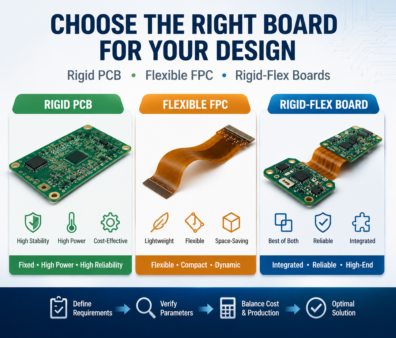
I. Rigid PCB: The Standard Choice for Fixed, High-Power Applications
Rigid PCBs, primarily using FR4 substrates, offer mature processes, stable structures, excellent heat dissipation, and superior electrical performance. They are the benchmark solution for non-bending, high-heat-dissipation, long-term continuous operation scenarios, with outstanding production yield and cost-effectiveness.
Substrate Grade and Operating Condition Matching (Quantified Standards)
Selection specifications are based on Tg (glass transition temperature) ratings to suit different industry loads and temperature conditions:
· Standard FR4 (Tg 130–140°C): Suitable for consumer electronics, home appliances, and other room-temperature, low-load scenarios.
· Mid-Tg FR4 (Tg ≥150°C): Suitable for general industrial control and intermittent, low-to-medium power equipment.
High-Tg FR4 (Tg ≥170°C): Suitable for industrial 24/7 continuous operation and automotive high-temperature, humid environments; resists thermal delamination and multiple reflow soldering cycles.
· High-Frequency Specialty Materials: With low Dk and low Df characteristics, used for RF, high-speed differential, and high-frequency communication circuits to effectively control impedance fluctuation, signal loss, and crosstalk.
Core Performance Quantified Metrics
· Mechanical Properties: Strong rigid support with no deformation; can directly carry various components of all sizes without the need for stiffeners.
· Electrical/Thermal Thresholds: Suitable for single-circuit continuous current ≥3A, local power dissipation ≥5W, long-term operation ≤125°C, and local temperature rise ≥85°C in high-power, high-heat scenarios. Complete ground planes and copper pouring for heat dissipation ensure stable PI performance and minimal voltage drop.
· Signal Performance: Stable dielectric parameters and controllable impedance support medium-to-high-speed transmission, making it the preferred substrate for high-speed and RF core circuits.
Production Advantages and DFM Design Rules
· Production Advantages: Standardized processes, short prototyping cycles, high production yields, and good fault tolerance. Suitable for mass production of double-layer, multi-layer, and high-frequency boards.
· Mandatory Risk Control Rules:
① No bending capability. Deformation will directly cause delamination and broken traces. Bending or irregular structures must not use rigid boards.
② High-power circuits must include complete ground planes and copper pouring for heat dissipation to avoid localized overheating and premature component aging.
③ Industrial, automotive, and high-temperature scenarios must use high-Tg (≥170°C) materials; standard FR4 is prohibited.
Applicable Scenarios and Typical Applications
Suitable for devices with fixed structures, no deformation, high heat dissipation requirements, high reliability, and strict cost control. Typical applications: high-power power supply boards, industrial PLCs, variable frequency drive boards, home appliance main control boards, server/router motherboards, automotive fixed electronic controls, medical fixed power supplies, etc., enabling long-term stable mass production.
II. Flexible FPC: The Dedicated Solution for Irregular, Confined Spaces and Dynamic Bending
FPCs use PI/PET flexible substrates, featuring thinness, light weight, 3D routing, curved surface lamination, and repeated bending capability. They are suitable for confined irregular spaces and dynamic folding structures. However, their heat dissipation and electrical performance have clear limitations; over-specification selection is prohibited.
Substrate Selection Breakdown
· PET Substrate: Low cost, suitable for static lamination, low-frequency bending, and low-life-expectancy consumer applications.
· PI Substrate: High temperature resistance, fatigue resistance, and stable insulation; the mainstream choice for high-end devices requiring high-frequency dynamic bending and long service life.
Quantified Operating Conditions and Bending Life Standards
· Electrical Limitations: Only suitable for single-circuit current ≤2A, single-zone power ≤3W, and room-temperature heat dissipation scenarios. Exceeding these limits can cause copper trace heating, substrate carbonization, and circuit breakage.
· Bending Life Classification:
① Standard FPC: 10,000–30,000 cycles, suitable for low-frequency hinges in home appliances.
② High-durability Gold-plated FPC: 50,000–100,000 cycles, suitable for high-frequency dynamic structures like wearables, foldables, and gimbals.
Performance Shortcomings and Constraints (SI/PI/Thermal Simulation)
① Very poor heat dissipation. FPCs are prohibited in areas where temperature rise exceeds 85°C.
② Poor high-frequency signal stability and high loss. FPCs are strictly prohibited for high-speed differential and RF core circuits.
③ Insufficient PI performance; high current easily causes abnormal voltage drop and power supply ripple. Does not support high-power scenarios.
④ No self-supporting capability; cannot independently carry SMD components or connectors.
Mandatory FPC DFM Production Specifications
① Heavy components like ICs and connectors must have steel sheet/PI stiffeners. Bare-board placement is prohibited to prevent pad tear-out, desoldering, and misalignment.
② Vias, pads, and components are prohibited in pure bending areas to avoid stress-concentration-induced breakage and delamination.
③ Trace width and spacing in dynamic bending areas should be 1.5 times larger than standard to reduce fatigue fracture risk.
④ Large copper pours on flexible boards must be strictly controlled to prevent thermal deformation from pulling on traces.
Applicable Scenarios and Typical Applications
Used in space-constrained, irregular-shaped, repeatedly folding, lightweight, highly integrated scenarios, replacing loose wiring harnesses to improve assembly efficiency. Typical applications: wearable device hinge cables, TWS earphone internal wiring, smartphone display/fingerprint cables, laptop hinges, camera flip cables, drone gimbals, medical endoscope probes, industrial micro-motion interconnect cables.
III. Rigid-Flex Boards: The Optimal Integrated Solution for High-End Composite Structures
Rigid-flex boards combine FR4 rigid sections with PI/PET flexible sections, offering both the stable high-power component mounting of rigid boards and the dynamic bending capability of FPCs. Specifically designed for "fixed component area + movable interconnect area" composite structures, they are suitable for high-end, highly integrated precision devices.
Zone-Based Quantified Performance
· Rigid Section: Comparable to high-Tg rigid board performance, supporting high power, high current, high heat dissipation, and high-speed signals.
· Flex Section: Strictly adheres to FPC operating thresholds, suitable only for low-to-medium current and room-temperature dynamic interconnection.
Exclusive DFM Risk Control Points
① The rigid-flex transition zone is a structural weak point. Stress-relief design is required; right-angle traces and dense vias are prohibited. Minimum bending radius ≥0.8mm.
② Copper pouring in the flex area must be limited to avoid tearing traces due to differential thermal expansion/contraction.
③ High design and process thresholds. Early confirmation of stack-up, board thickness, bending tolerances, and lamination processes is required to avoid structural defects in mass production.
Applicable Scenarios and Typical Applications
Suitable for high-end devices with stringent form factor, integration, and reliability requirements, and adequate budget: foldable device main interconnect boards, camera body-lens adapter boards, portable precision inspection instruments, minimally invasive medical control boards, high-end smart lock hinge-integrated boards, precision industrial inspection equipment.
Core Disadvantages: Complex design, long process lead times, and highest mass-production cost. Not suitable for general low-cost, high-volume projects.
IV. Industry Reliability Compliance Classification (Baseline for Precise Scenario Selection)
Clear selection baselines are defined by industry standards to prevent downgraded selection or over-design:
· Consumer Electronics: RoHS compliant, standard temperature/humidity conditions, cost-optimized solution preferred.
· Industrial Equipment: High-Tg materials mandatory; resistant to humidity, heat, aging, and vibration; supports 24/7 continuous operation.
· Medical Devices: Compliant with ISO 13485; high insulation, low outgassing, high stability; high-durability PI-FPC/rigid-flex preferred for miniature flexible scenarios.
· Automotive Equipment: Tg ≥170°C materials mandatory; withstands high-temperature shock and strong vibration; rigid boards for fixed areas, high-durability FPC for dynamic areas.
V. Three-Tier Engineering Selection Model
Replacing experience-based selection with a tiered, mandatory veto process:
· Tier 1 – Mandatory Veto: Bending/irregular shape requirement → veto rigid board; High power/high temperature/high-speed RF requirement → veto FPC.
· Tier 2 – Matching Verification: Check temperature range, current/power consumption, signal rate, bending life, and compliance grade for parameter compatibility.
· Tier 3 – Cost & Production Verification: Balance performance and cost based on production volume, lead time, and process tolerance to finalize the optimal solution.
VI. Comprehensive Industry Scenario Matching Summary
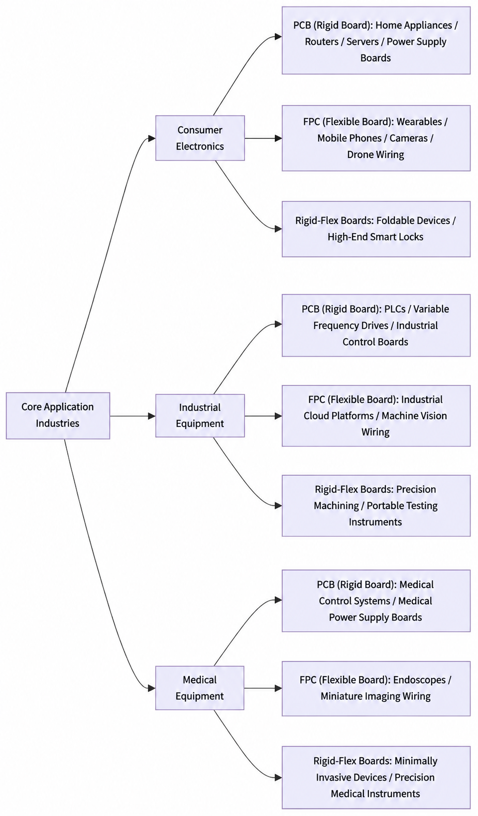

Consumer Electronics (Thin, highly integrated, cost-controlled mass production)
· Rigid PCB: Routers, servers, home appliance main controls, high-power power supplies, automotive fixed electronic controls (fixed, heat-dissipating, non-bending scenarios).
· FPC: Display/fingerprint cables, foldable devices, smart wearables, TWS earphones, laptop hinges, gimbal cables (confined, high-frequency bending scenarios).
· Rigid-Flex: Foldable devices, high-end smart locks, consumer-grade precision inspection instruments (fixed SMT + local bending composite scenarios).
Industrial Equipment (High stability, long life, anti-interference)
· Rigid PCB: PLCs, variable frequency drives, industrial high-power supplies, industrial main control boards (high current, high heat dissipation, 24/7 continuous operation).
· FPC: Industrial micro-camera cables, small gimbal hinges, narrow-device interconnects (micro-movable structures).
· Rigid-Flex: High-end precision industrial controls, portable industrial inspection instruments (stability + irregular assembly).
Medical Devices (High precision, miniaturization, high reliability)
· Rigid PCB: Medical main control boards, medical power supplies/drives (fixed chassis power supply and heat dissipation).
· FPC: Endoscope probes, small medical inspection bending cables (miniature insertion, curved surface lamination).
· Rigid-Flex: Minimally invasive medical control boards, high-end precision inspection instruments (high-precision SMT + local bending assembly).
VII. Comprehensive Parameterized Selection Reference Table

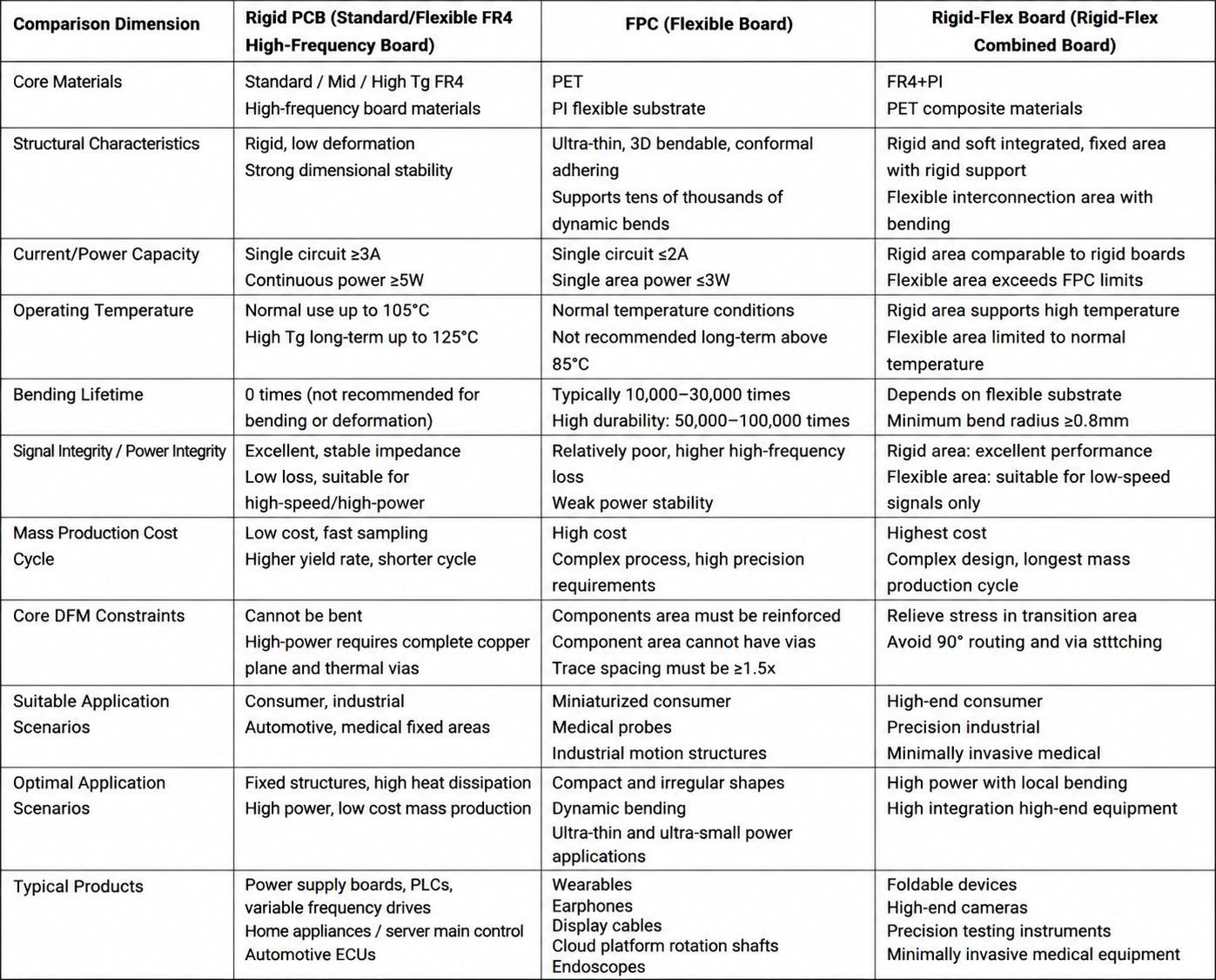
Board selection is not about hierarchical superiority; the core principles are parameter matching, operating condition compliance, DFM controllability, and optimal cost. Rigid PCBs suit high-power, high-stability, low-cost mass-production scenarios. FPCs address irregular, confined spaces and dynamic bending for lightweight, integrated needs. Rigid-flex boards meet the composite structural integration needs of high-end devices. Strictly implementing the three-tier selection model and quantified operating condition red lines prevents selection errors, design rework, and production risks from the start, providing standardized technical support for product development, process review, and mass production scale-up.
trending news
Contact Us