


Sorry, no sales person is available right now to take your call. Pls leave a message and we will reply to you via email as soon as possible.
Comprehensive Guide to Common PCB Substrate Materials for RF/Microwave Systems
2026-08-17
Printed circuit board (PCB) dielectric substrates are the core physical carriers of RF and microwave circuits. They not only provide component mounting and electrical interconnection but fundamentally determine the transmission quality of high-frequency signals. In the RF and microwave bands, substrate parameters such as dielectric constant (Dk), dissipation factor (Df), temperature stability, and thermal conductivity directly affect circuit insertion loss, voltage standing wave ratio (VSWR), phase consistency, and overall thermal reliability. Substrate selection has thus become a critical decision-making step in high-frequency circuit design.
Drawing on the engineering expertise accumulated by Kinji Group in high-frequency RF PCB material selection, process optimization, and volume production, this article systematically reviews the material characteristics and selection logic of mainstream substrates, providing a standardized reference for RF/microwave circuit design and mass production.
I. FR-4 Glass Epoxy Laminate
Base Material: A composite insulating board formed by impregnating flame-retardant epoxy resin into glass-fiber fabric reinforcement, cured under high-temperature lamination.
Key High-Frequency Characteristics: FR-4 is a general-purpose low-frequency insulating material. It offers mature manufacturing processes, good mechanical strength, low cost, and excellent insulation properties as well as processing adaptability, making it suitable for large-scale standardized PCB fabrication. However, its high-frequency performance has notable shortcomings: in the GHz range, its dissipation factor exceeds 0.015, causing severe signal attenuation; its dielectric constant also drifts significantly with frequency, temperature, and humidity, making impedance control and phase stability inadequate for high-frequency requirements.
Application Scenarios: Suitable only for DC, low-frequency analog, and digital circuits. Widely used in consumer electronics, industrial control boards, switching power supplies, low-frequency signal acquisition, and other applications with no high-frequency performance requirements. Not recommended for any RF/microwave signal path; may only be used in low-frequency auxiliary or power management sections. Leveraging its mature volume-production system, Kinji Group utilizes FR-4 as the primary substrate for general low-frequency circuit boards, ensuring high yield and cost-effective delivery.
II. Rogers High-Frequency Laminates (RO4003C / RO4350B)
Base Material: PTFE-based composites modified with inorganic fillers, reinforced with specialized glass-fiber systems — the industry-standard high-frequency substrates for commercial RF circuits.
Key High-Frequency Characteristics: This series is the benchmark for medium-low-loss high-frequency materials in the industry, featuring highly stable dielectric constants, low high-frequency losses, and minimal temperature coefficients. Within conventional microwave bands, signal insertion loss is well controlled and phase consistency is excellent. They are compatible with conventional PCB lamination, etching, and drilling processes, overcoming the processing difficulties and poor manufacturability of pure PTFE materials. They strike an optimal balance between high-frequency electrical performance and industrial-scale production capability, making them the most cost-effective substrate choice in the civilian RF sector.
Application Scenarios: Widely used in 4G/5G communications RF units, microwave transmission modules, IoT high-frequency antennas, RF filters, power dividers, couplers, base-station front-end circuits, and other mid-to-high-end commercial RF equipment. Kinji Group has completed standardized process adaptation for this series, leveraging high-frequency hybrid lamination and high-precision line control to effectively address common volume-production challenges such as layer misalignment, delamination, and abnormal insertion loss, ensuring consistent batch-to-batch quality for commercial RF projects.
III. RT/Duroid® High-Frequency Substrates
Base Material: High-performance modified PTFE-based composite laminates manufactured with precision-homogeneous filler technology, positioned for premium microwave applications.
Key High-Frequency Characteristics: These materials feature extremely low dielectric loss, minimal moisture absorption, and exceptional dielectric uniformity. At ultra-high frequencies and over broadband microwave conditions, signal attenuation is minimal, phase noise is low, and transmission accuracy is exceptionally high. Their thermal stability is outstanding, with electrical parameters showing minimal variation across wide temperature ranges, meeting the stringent demands of ultra-wideband, high-precision, low-noise microwave circuits.
Application Scenarios: Focused on high-performance microwave systems, such as microwave detection equipment, satellite communication front-end modules, precision radar signal-processing circuits, broadband high-frequency test instruments, and other premium civilian and semi-military applications that demand ultra-low loss, phase accuracy, and band stability. Recognizing the increased processing difficulty of these ultra-low-loss materials, Kinji Group has developed specialized precision manufacturing solutions (including drilling, lamination, and surface finishing) to effectively ensure signal integrity and batch consistency for ultra-wideband microwave circuits.
IV. Ceramic Substrates (Alumina Al₂O₃ / Aluminum Nitride AlN)
Base Material: High-purity alumina or aluminum nitride inorganic ceramic sintered rigid substrates, containing no organic resin components.
Key High-Frequency Characteristics: Ceramic substrates represent the top tier of specialty RF materials, combining ultimate electrical stability with immunity to interference. Dielectric loss approaches theoretical limits, insulation strength is high, thermal resistance is excellent, and aging resistance is superior. Parameter variations under complex electromagnetic environments and extreme temperature changes are minimal. Alumina (Al₂O₃) offers better cost-effectiveness and suits conventional high-precision RF circuits, while aluminum nitride (AlN) provides ultra-high thermal conductivity, effectively addressing thermal-dissipation bottlenecks in high-power high-frequency circuits. Ceramic substrates also offer extremely high dimensional accuracy, facilitating dense microstrip-line layouts.
Application Scenarios: Exclusively used in high-end defense, aerospace, and similar fields, including military radar high-frequency assemblies, satellite precision RF circuits, high-power microwave devices, high-accuracy RF sensors, and core military communication modules — applications with extreme requirements for reliability, environmental adaptability, and power density. Leveraging mature specialty precision processes, Kinji Group delivers high-accuracy line patterning and custom volume production for both alumina and aluminum nitride ceramic substrates, meeting the rigorous manufacturing demands of high-end RF components.

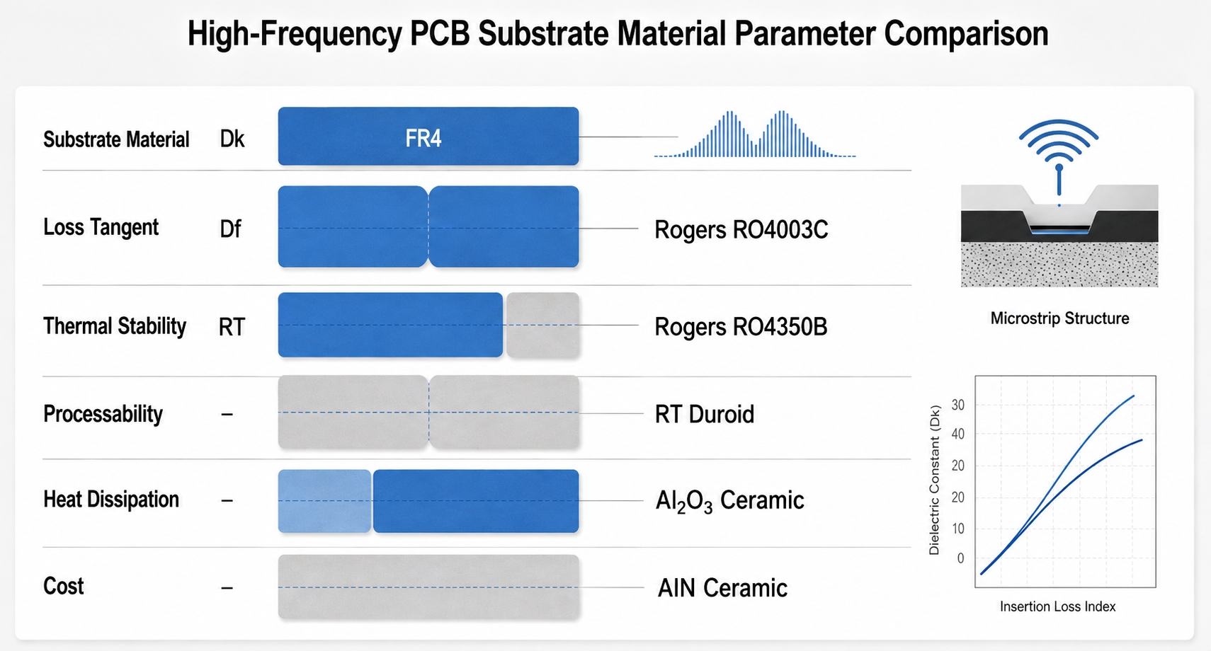
V. Comparative Summary of Core Parameters for Four RF/Microwave PCB Substrates
To facilitate rapid material selection by design engineers, the following table compares the key high-frequency parameters, process characteristics, and application scenarios of the four substrate categories. Performance ratings follow a uniform five-tier standard: Poor (unsuitable for high frequency), Fair (basic usability), Good (cost-effective for commercial high frequency), Excellent (reliable for high-end commercial use), and Superior (military/aerospace-grade extreme performance).

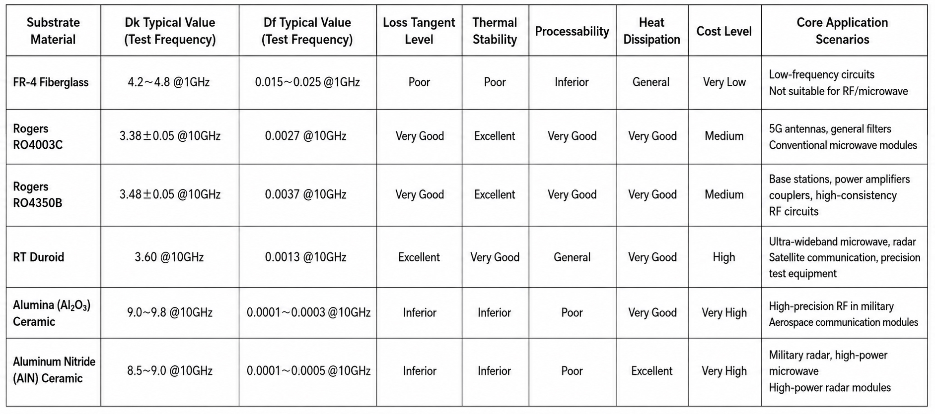
Note: Dk and Df values in the table are typical engineering parameters from original manufacturers (FR-4 at 1 GHz; others at 10 GHz). Actual values may vary slightly by batch, thickness, and processing. Selection should consider operating frequency, power level, accuracy requirements, and production costs comprehensively.
VI. High-Frequency FAQ for RF/Microwave PCB Substrate Selection
Drawing on Kinji Group’s extensive engineering experience, the following addresses common challenges encountered in RF/microwave circuit design and volume production, providing professional answers to facilitate the transition from theory to production.
Q1: Why is FR-4 unsuitable for RF/microwave signal paths, only for low-frequency auxiliary circuits?
A: The fundamental reason lies in FR-4’s poor high-frequency electrical performance. Its Df exceeds 0.015 in the GHz range, resulting in significant dielectric loss and thermal dissipation — leading to large insertion loss and amplitude attenuation. Moreover, its Dk drifts considerably with frequency, temperature, and humidity, causing microstrip impedance shifts, phase distortion, and VSWR degradation — all of which violate the basic requirements of low-loss and high-phase-consistency signal transmission. Therefore, FR-4 must be confined to low-frequency control or power-supply sections and must never be placed in high-frequency signal paths.
Q2: How should one choose between Rogers RO4003C and RO4350B?
A: Both are mainstream medium-to-low-loss high-frequency laminates, yet they differ in emphasis. RO4003C offers a lower Dk and slightly better loss performance with excellent cost-effectiveness, suitable for general antennas, common filters, and conventional microwave modules. RO4350B, by contrast, provides higher rigidity, better lamination stability, and superior flatness, making it more appropriate for multi-layer hybrid lamination, high-consistency power dividers, couplers, and base-station RF core units where structural stability is critical. Selection should match the operating band, precision targets, and production scale, with careful consideration of hybrid-lamination processes.
Q3: What are the comparative advantages and disadvantages of PTFE-based high-frequency boards (Rogers/RT/Duroid) vs. ceramic substrates?
A: PTFE-based composite boards offer the advantage of compatibility with standard PCB processes (lamination, etching, drilling), lower processing difficulty, strong manufacturability, controllable cost, and better toughness than ceramics — less prone to edge chipping or cracking — making them suitable for large-area, multi-layer circuits in volume production. Their disadvantages include lower temperature limits, reduced EMI immunity, less dimensional precision, and inferior long-term thermal stability compared to ceramics. In ultra-high-power, extreme-temperature, or military-grade electromagnetic environments, PTFE boards lack sufficient performance margin. The choice should be based on actual operating conditions, performance specifications, and production needs.
Q4: For high-precision microwave or broadband RF circuits, should RT/Duroid or conventional Rogers be prioritized?
A: RT/Duroid is the preferred choice. It features lower dielectric loss, ultra-low moisture absorption, and exceptional dielectric uniformity, with minimal parameter variation across wide frequency ranges — leading to low phase noise and high transmission accuracy. It is ideally suited for ultra-wideband radar, satellite communications, and high-precision test equipment. Conventional Rogers materials lag behind in broadband consistency and ultra-low-loss performance, and are adequate only for general-purpose RF requirements.
Q5: What are the key selection criteria between alumina and aluminum nitride ceramic substrates?
A: Both are ultra-low-loss, ultra-stable military-grade materials; the primary difference lies in thermal dissipation capability. Alumina (Al₂O₃) offers better cost-effectiveness and mature processing, with moderate thermal conductivity, suitable for general medium-to-low-power high-precision RF devices. Aluminum nitride (AlN) features ultra-high thermal conductivity, specifically designed for high-power, high-heat-flux aerospace and defense microwave modules, effectively resolving thermal-failure issues in high-power high-frequency circuits.
Q6: Between dielectric constant (Dk) and dissipation factor (Df), which is more important in material selection?
A: Both are core parameters in high-frequency selection; neither can be neglected. Dk determines impedance matching, wavelength dimensions, and layout — forming the foundation for structural design and simulation. Df determines insertion loss, thermal dissipation, and signal fidelity, directly impacting overall system efficiency and signal quality. Low-frequency circuits may prioritize Dk stability, while high-frequency, ultra-high-frequency, and high-precision circuits must simultaneously control Dk consistency and minimize Df loss. Engineering decisions should integrate simulation results, operating conditions, and process constraints comprehensively.
VII. Engineering Mnemonic for RF/Microwave PCB Substrate Selection (Quick Reference)
General Rule:
· For low cost at low frequency, FR-4 is the way;
· For commercial RF, Rogers holds sway;
· For high-precision broadband, Duroid is key;
· For military heat and power, ceramics are the key.
Material-Specific Mnemonic:
· FR-4: Lowest cost for low-frequency boards, high-frequency loss it can't afford; control and power use it fine, but stay away from RF design.
· Rogers: Medium loss but stable and sound, mass-production-friendly and cost-renowned; for comms and mid-to-high RF bands, antennas and filters it commands.
· RT/Duroid: Ultra-low loss and high precision true, broadband microwave noise subdued; for probes, satellites, and precision test, premium civilian use is best for you.
· Ceramics: Ultra-low loss and steady strong, heat-resistant and noise-free all along; alumina for general high-end needs, AlN for heat that exceeds all creeds.
Selection Essence:
· Low-frequency, low-cost, general mass production → FR-4
· Commercial high-frequency, low insertion loss, high phase consistency → Rogers series
· Ultra-wideband, low-noise, high-precision microwave → RT/Duroid
· Extreme environments, high-power, military/aerospace rigorous conditions → Ceramic substrates
Actual decisions must integrate electrical characteristics, process compatibility, and supply-chain conditions — balancing performance, yield, and cost. Customized material selection and process-optimization solutions can be facilitated through collaboration with professional technical teams.
Compiled from Kinji Group engineering practice.
Data in this document is based on manufacturers’ typical parameters; actual applications should be confirmed through project-specific requirements and batch-validation results.
Previous Article: The Role of Flex PCB in Automotive Electronics
trending news
Contact Us