

Sorry, no sales person is available right now to take your call. Pls leave a message and we will reply to you via email as soon as possible.
PCB Stator Technology for Next‑Gen Electric Drive Design
2025-11-14
What Is a Motor Stator?
The stator is the stationary part of an electric motor. Working hand‑in‑hand with the rotor, it converts electrical energy into mechanical motion through electromagnetic induction. Think of it as the “command center” of the motor—it generates the magnetic field that sets the rotor in motion.
Core Components
In traditional radial flux motors, the stator is built from two essential parts: the iron core and the windings.
Stator Core
- Role: Forms the main magnetic circuit, guiding flux efficiently and strengthening the field.
- Material: Laminated silicon steel sheets.
- Why silicon steel? Silicon increases resistivity, reducing eddy current losses in alternating fields.
- Why lamination? Thin sheets, stacked and insulated, block eddy current paths and minimize iron losses.
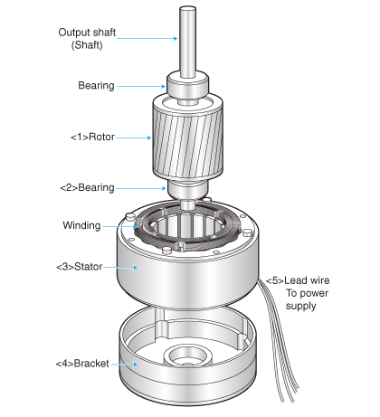
Figure 1. Schematic Diagram of Motor Structure
Stator Windings
- Role: When AC current flows, windings generate the rotating magnetic field that drives the rotor.
- Material & Process: Insulated copper or aluminum wires embedded in slots. Connection methods (star or delta) define motor characteristics.
Frame / Housing
- Provides mechanical support, protects the stator, and often includes cooling fins to manage heat.
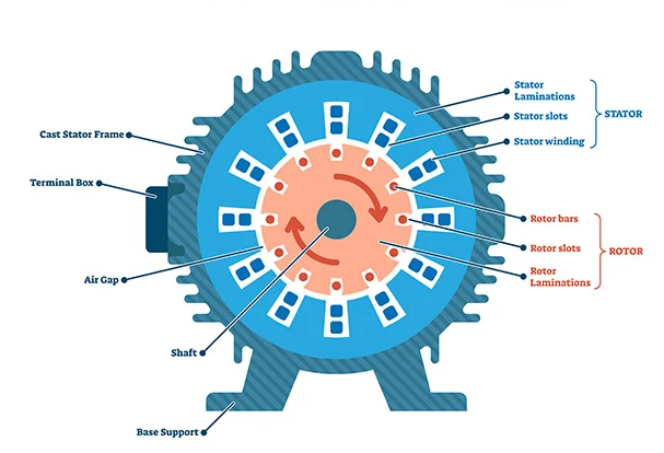
Figure 2. Composition of Motor Stator and Rotor
Why PCB Technology for Stators?
Switching to PCB stator technology is not just a process tweak—it’s a fundamental shift from mechanical winding to electronic printing. This change tackles long‑standing bottlenecks in motor design and offers four decisive advantages:
- Ultra‑flat design & high power density: PCB stators enable thin, planar structures, making axial flux motors compact yet powerful.
- Precision & consistency: Photolithography and etching deliver micron‑level accuracy, eliminating human error and ensuring uniform performance—perfect for mass production.
- High‑frequency efficiency: Air‑core or light‑core designs remove iron losses, boosting efficiency in high‑speed, high‑frequency applications.
- Integration & cost potential: PCB stators can embed drive electronics, sensors, and communication interfaces, simplifying assembly and reducing system costs at scale.
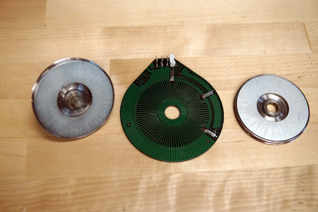
Figure 3. PCB Stator in a DC Axial Flux Motor
From Niche to Mainstream: The Commercial Journey
Phase 1: Niche Entry – Handheld & Low‑Power Devices Early
Early applications included drones, portable medical devices, and servo actuators, where torque, size, and weight were critical. PCB stators delivered higher torque in smaller, lighter packages.
Phase 2: Technology Validation – Wind Power Exploration
In 2012, Boulder Wind Power (BWP) tested PCB stators in megawatt‑scale turbines. Their goal was to build multi‑meter stators with PCB precision, avoiding heavy winding processes. Despite challenges, this milestone proved scalability and drew industry attention.
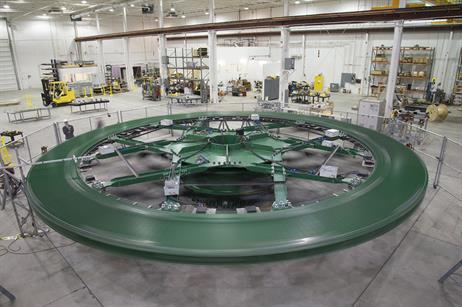
Figure 4 . PCB Stator Applied in Wind Turbine Generators
Phase 3: Mainstream Breakthrough – Electric Mobility & Advanced Equipment
With EVs, e‑ships, e‑aircraft, and robotics booming, performance demands soared. PCB axial flux motors offered high torque density, enabling wheel‑hub drives and reshaping layouts. Lightweight, efficient designs extended range and improved dynamics. PCB stators became synonymous with high performance.
Core Advantages of PCB Stators
- Consistency: Automated PCB manufacturing ensures identical winding geometry, eliminating variability.
- Thermal Stability & Reliability: Copper, fiberglass, and epoxy with matched expansion rates reduce stress under thermal cycling, extending lifespan.
- Integration & Miniaturization: Sensors and control circuits can be embedded directly, simplifying systems and reducing wiring.
- Lifecycle Value: Optimized winding reduces copper usage; air‑core design eliminates iron losses, boosting efficiency. Longer lifespan and reduced maintenance lower total cost of ownership.
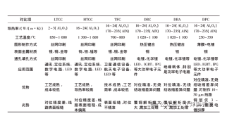
Manufacturing Challenges and Solutions
In the pattern imaging stage, achieving micron-level precision is critical. Even slight deviations can lead to imbalance in winding resistance and inductance, causing torque ripple and reduced efficiency. To address this, high-precision laser direct imaging is used, along with strict process compensation to ensure uniformity across phases.
Pattern Imaging
Precision is critical. Even small deviations in winding geometry can cause uneven resistance, torque ripple, and efficiency loss. The solution is high‑precision laser direct imaging combined with strict process compensation to ensure uniformity.
Etching Thick
copper layers make etchant exchange difficult, increasing side‑etching risks and line width errors. Engineers address this with multi‑stage rapid etching and design compensation, ensuring final dimensions meet specifications.
Multilayer Lamination
Challenges include resin filling, layer alignment, and curing. High‑flow prepregs are used to fill gaps, mechanical pinning prevents misalignment, and optimized curing cycles ensure complete resin solidification even with thick copper layers.
Mechanical Drilling
Thick boards (≥2.0 mm) increase drilling resistance, leading to tool wear and rough hole walls. Solutions include staged drilling (pilot holes followed by enlargement) and adjusted feed rates to protect hole quality and extend tool life.
Solder Mask Printing
Large height differences between copper and substrate can cause poor ink coverage, leading to defects such as pinholes or bubbles. Diluted high‑viscosity inks and multi‑pass printing ensure uniform insulation layers with reliable coverage.
Conclusion
PCB stator technology is a paradigm shift in motor manufacturing—transforming copper winding into printed circuits. Its benefits span consistency, reliability, integration, and efficiency, far beyond traditional designs. To unlock stable mass production, however, motor design and PCB fabrication must work hand‑in‑hand.
Previous Article: Fabrication and Reliability of Si₃N₄ Ceramic Copper‑Clad Substrates
Next Article: PCB Stator Technology for Next‑Gen Electric Drive Design
trending news
Contact Us